Current Location: YF Zhichengjia > Product Center > Thread Inserts > Wire Thread Insert >
Introduction to Wire Thread Inserts
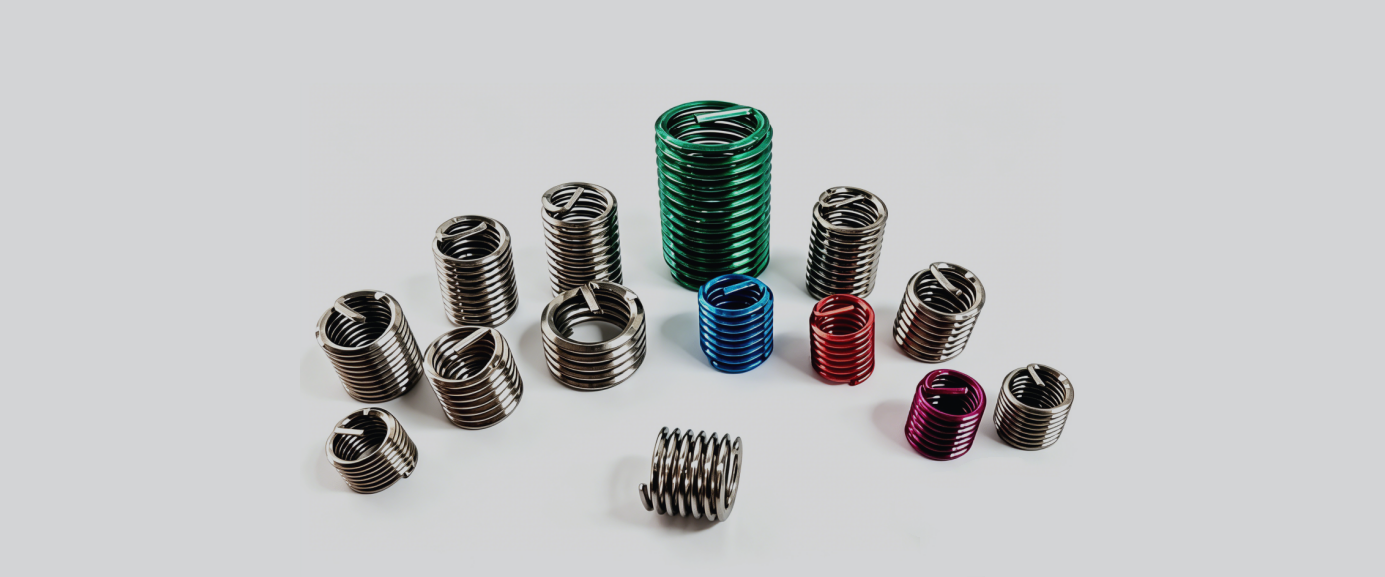
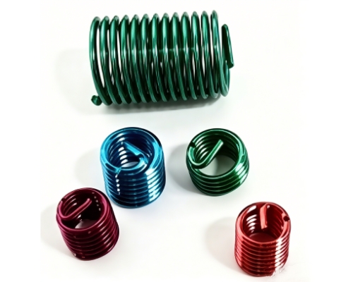
A new type of internal threaded fastener. An embedded thread reinforcement element made of high-strength stainless steel wire. Its performance is superior to internal threads formed by direct tapping. Used to repair or reinforce threaded holes in soft materials (such as aluminum, magnesium, plastics) to provide high strength, wear resistance, and anti-loosening properties.
Product Advantages
1. Wire thread inserts are lightweight and strong, typically made of hardened stainless steel 304 with a hardness of HRC43-50 and a material strength of not less than 1370Mpa.
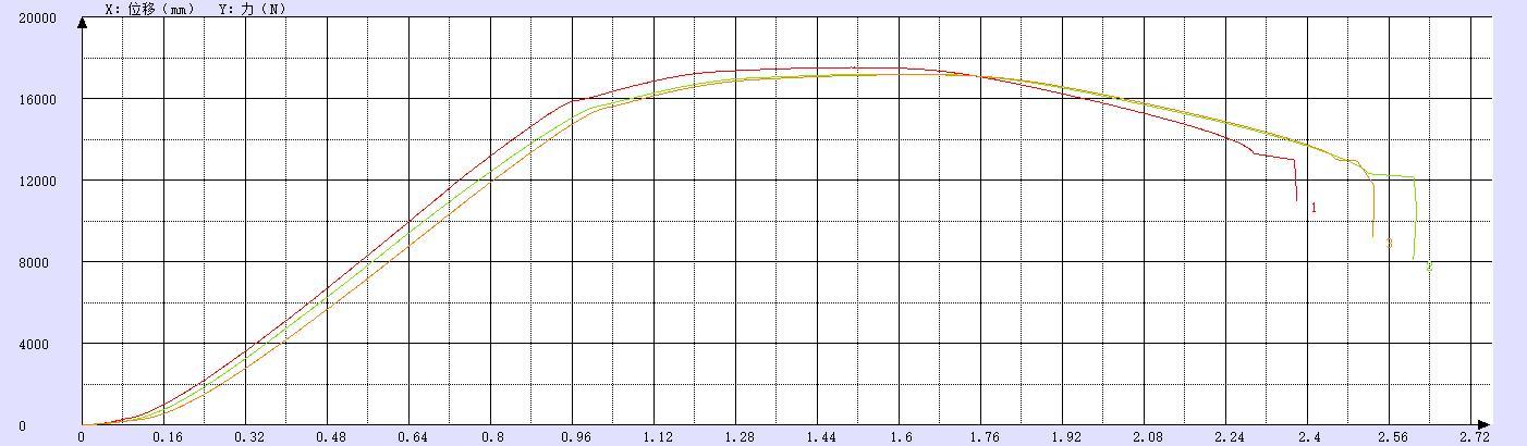
Tensile Strength Test Chart of Wire Thread Insert Material
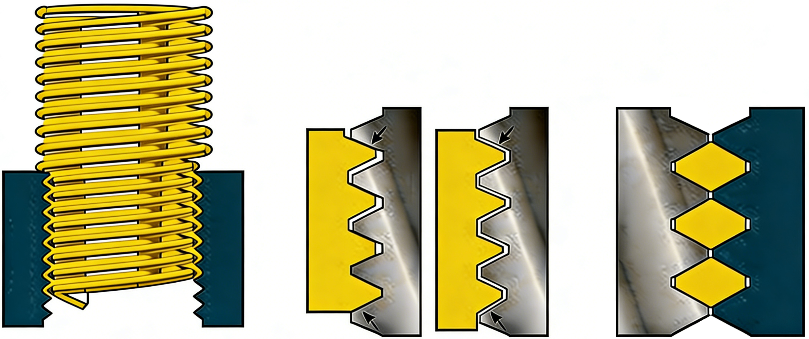
2. Wire thread inserts can effectively upgrade the internal thread strength of light alloy (magnesium, aluminum, etc.) materials to Grade 12. Meanwhile, the use of wire thread inserts distributes the stress on internal threads more evenly; normally, the first thread bears 50% of the load without inserts.
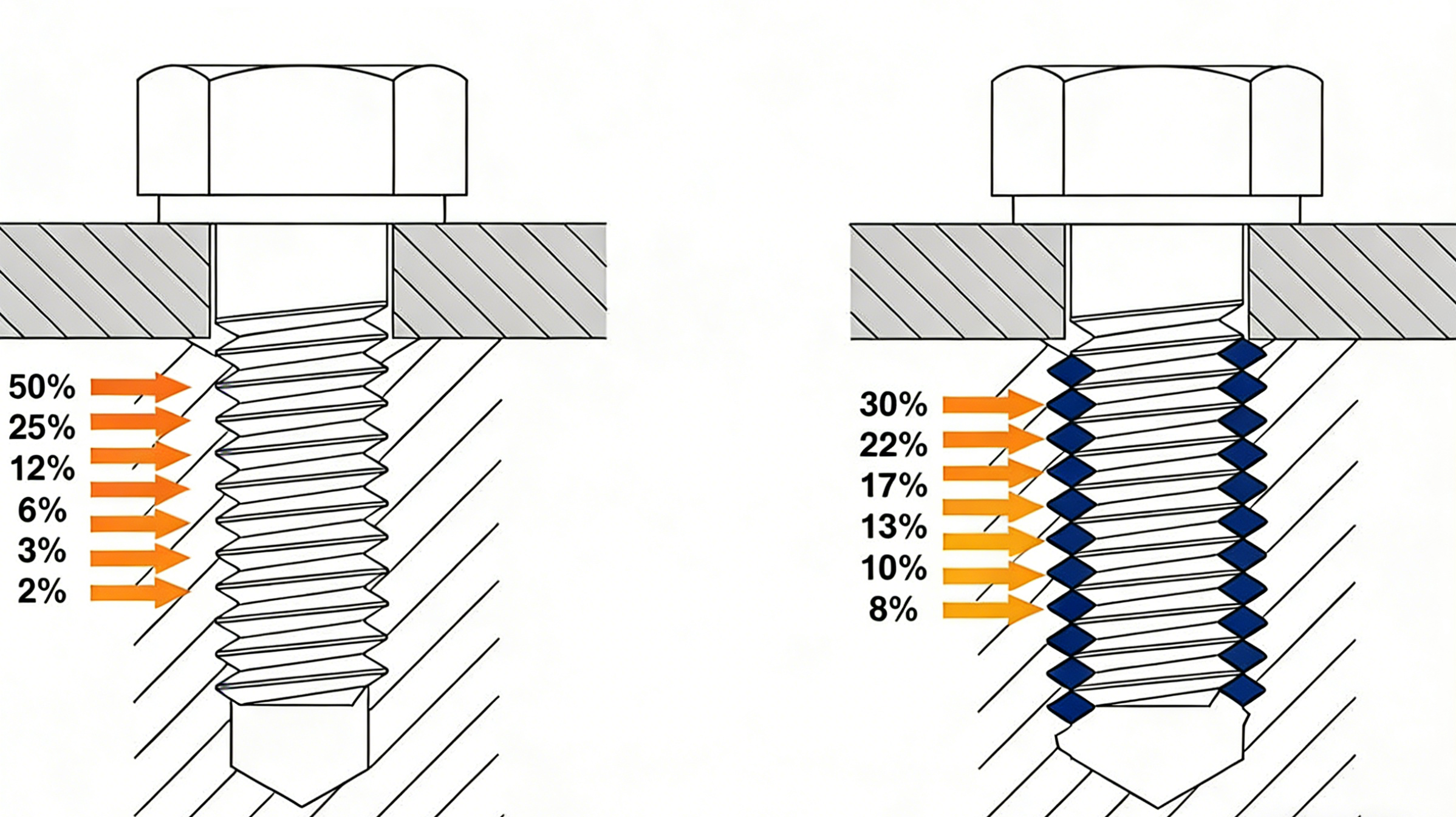
Standard Threaded Hole Threaded Hole with Wire Thread Insert
These two advantages allow light alloy threaded holes fitted with wire thread inserts to adapt to high-strength bolts above Grade 8.8.
Product Working Procedure
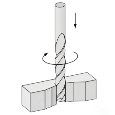
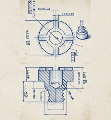
1. Drilling: Use a standard twist drill and pay attention to diameter selection. Avoid counterboring if possible.
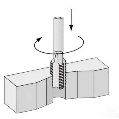
2. Tapping: Use the correct tap to thread the base material for the selected thread size.
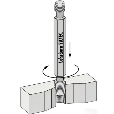
3. Thread Inspection: Use gauges to inspect the base threads if required.
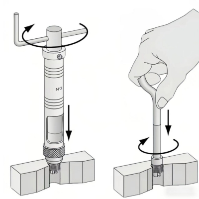
4. Installation: Screw the wire thread insert directly into the base thread. The end of the insert should be screwed at least 1/4 turn below the material surface.
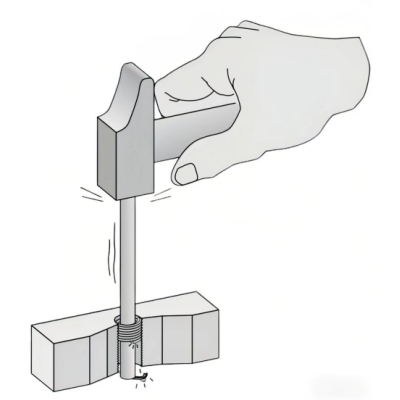
5. Tang Breaking: For through holes, use a tang break-off tool to snap the tang. For wire thread inserts in blind holes, the tang can remain in place if maximum screwing depth is required.
6. Inspection: Re-inspect after removing the tang.
Note: Step 5 can be omitted for lock-free wire thread inserts.
Product Installation Notes
The keys to installation are vertical screwing, matching tools, and stopping when in place
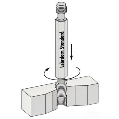
1. Positioning & Screwing: Install the insert into a special wrench, align it with the tapped base hole, screw it in vertically to partially insert the insert.
2. Avoid Errors: As shown in the diagram, ensure the wrench is vertical to avoid skew caused by "angle issues"; use taps with matching pitch to avoid "pitch issues" that prevent screwing or thread jumping.
3. Full Installation: As shown in the diagram, screw the insert to the specified depth (usually leaving about one pitch at the hole opening), with the tang exposed for subsequent processing.
Tool Display
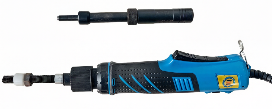
Installation Tool
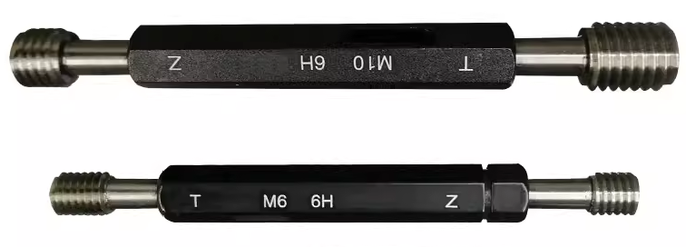
Inspection Tool
Product Features
1. Materials include stainless steel SUS304, SUS316, phosphor bronze, and high-temperature resistant INCONEL nickel alloy.
2. Surface treatments include lubrication, tin plating, zinc plating, and silver plating (for high-temperature requirements).
3. Sizes range from M2 to M39.
4. Threads include coarse and fine threads.
5. Lengths include 5 standard specifications: 1D, 1.5D, 2D, 2.5D, 3D; customized lengths are also available.
6. Types include standard and lock-free.
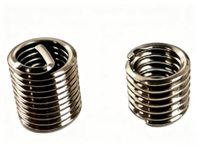
7. Two styles: with tang and tang-free.
8. Appearance colors can be red, green, etc., as required.
Industry Applications
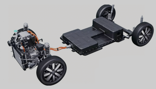
New Energy Vehicle Industry
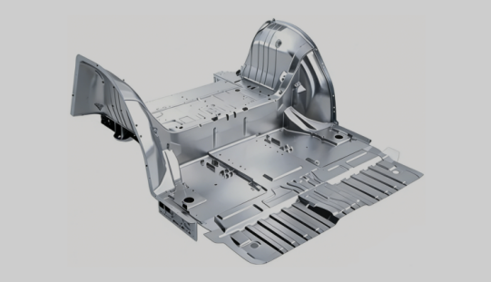
Light Alloy Industry

Embodied Intelligence Industry

HPC AI Server Industry

Industrial Electronics Industry

Consumer Electronics Industry
Low-Altitude Economy Industry

Aerospace Industry
Wire Thread Insert Standards
Table 1 Metric Thread Tap Drill & Thread Depth Details
Table 1 Metric Thread Tap Drill & Thread Depth Details
| Metric Coarse Thread | Pitch | Tap Drill d | Drilling Depth T | Thread Depth D | Metric Fine Thread | Pitch | Tap Drill | Drilling Depth | Thread Depth |
|---|---|---|---|---|---|---|---|---|---|
| M2.0 | 0.4 | 1.6 | 6 | 4 | M2.5 | 0.35 | 2.2 | 6 | 4 |
| M2.2 | 0.45 | 1.75 | 6 | 4 | M3.5 | 0.35 | 2.7 | 8 | 6 |
| M2.3 | 0.45 | 1.9 | 6 | 4 | M4.0 | 0.5 | 3.5 | 9 | 7 |
| M2.5 | 0.45 | 2.1 | 7 | 4.5 | M4.5 | 0.5 | 4 | 9 | 7 |
| M2.6 | 0.45 | 2.2 | 7 | 4.5 | M5.0 | 0.5 | 4.5 | 14 | 11 |
| M3.0 | 0.5 | 2.5 | 8 | 6 | M5.5 | 0.5 | 5 | 14 | 11 |
| M3.5 | 0.6 | 2.9 | 8 | 6 | M6.0 | 0.75 | 5.3 | 15 | 12 |
| M4.0 | 0.7 | 3.3 | 9 | 7 | M7.0 | 0.75 | 6.3 | 15 | 12 |
| M4.5 | 0.75 | 3.25 | 9 | 7 | M8.0 | 1 | 7 | 18 | 15 |
| M4.5 | 0.75 | 3.8 | 10 | 8 | M8.0 | 0.75 | 7.3 | 18 | 15 |
| M5.0 | 0.8 | 4.2 | 14 | 11 | M8.5 | 0.75 | 7.3 | 18 | 15 |
| M5.0 | 0.9 | 4.1 | 14 | 11 | M9.0 | 0.75 | 8 | 18 | 15 |
| M6.0 | 1 | 5 | 15 | 12 | M9.0 | 0.75 | 8.3 | 18 | 15 |
| M7.0 | 1 | 6 | 15 | 12 | M10.0 | 1.25 | 8.8 | 20 | 17 |
| M8.0 | 1.25 | 6.8 | 18 | 15 | M10.0 | 0.75 | 9 | 20 | 17 |
| M9.0 | 1.25 | 7.8 | 18 | 15 | M11.0 | 0.75 | 9.3 | 20 | 17 |
| M10.0 | 1.5 | 8.5 | 20 | 17 | M11.0 | 1.25 | 10.3 | 20 | 17 |
| M11.0 | 1.5 | 9.5 | 20 | 17 | M12.0 | 1.25 | 10.8 | 20 | 17 |
| M12.0 | 1.75 | 10.3 | 20 | 17 | M12.0 | 1.25 | 10.8 | 20 | 17 |
| M14.0 | 2 | 12 | 25 | 22 | M12.0 | 1.25 | 10.8 | 20 | 17 |
| M16.0 | 2 | 14 | 25 | 22 | M14.0 | 1.5 | 12.5 | 25 | 22 |
| M18.0 | 2.5 | 15.5 | 25 | 22 | M15.0 | 1.5 | 13.5 | 25 | 22 |
| M20.0 | 2.5 | 17.5 | 25 | 22 | M16.0 | 1.5 | 14.5 | 25 | 22 |
| M22.0 | 2.5 | 19.5 | 25 | 22 | M20.0 | 1.5 | 15 | 25 | 22 |
| M24.0 | 3 | 21 | 25 | 22 | M22.0 | 2 | 18 | 25 | 22 |
| M27.0 | 3 | 24 | 25 | 22 | M24.0 | 2 | 18 | 25 | 22 |
| M30.0 | 3.5 | 26.5 | 25 | 22 | M27.0 | 2 | 16.5 | 25 | 22 |
| M33.0 | 3.5 | 29.5 | 25 | 22 | M30.0 | 2 | 16.5 | 25 | 22 |
| M36.0 | 4 | 32 | 25 | 22 | M33.0 | 2 | 16.5 | 25 | 22 |
| M39.0 | 4 | 35 | 25 | 22 | M36.0 | 2 | 16.5 | 25 | 22 |
Wire Thread Insert Standards
Table 2 GB/T 24425.1-2009 Wire Thread Insert Parameters---(Coarse Thread)
Table 2 GB/T 24425.1-2009 Wire Thread Insert Parameters---(Coarse Thread)
| Wire Thread Insert Specification | Guide Size dy | Free State Diameter Dz | Nominal Length n*p | Free State Coils N (min) | Installed Length | ||||
|---|---|---|---|---|---|---|---|---|---|
| min | max | min | max | min | max | min | max | ||
| M2 | 2.53 | 2.7 | 1d | 3 | 3.4 | 1.6 | 1.8 | ||
| 1.5d | 5.3 | 5.6 | 2.6 | 2.8 | |||||
| 2d | 7.6 | 7.9 | 3.6 | 3.8 | |||||
| 2.5d | 9.9 | 10.2 | 4.6 | 4.8 | |||||
| 3d | 12.2 | 12.4 | 5.5 | 5.8 | |||||
| M2.5 | 3.2 | 3.7 | 1d | 3.3 | 3.8 | 2.05 | 2.375 | ||
| 1.5d | 5.9 | 6.3 | 3.3 | 3.525 | |||||
| 2d | 8.5 | 8.8 | 4.55 | 4.775 | |||||
| 2.5d | 11.1 | 11.4 | 5.8 | 6.025 | |||||
| 3d | 13.6 | 13.9 | 7.05 | 7.275 | |||||
| M3 | 3.8 | 4.35 | 1d | 3.6 | 4.3 | 2.5 | 2.75 | ||
| 1.5d | 6.3 | 7.1 | 4 | 4.25 | |||||
| 2d | 9 | 9.8 | 5.5 | 5.75 | |||||
| 2.5d | 11.8 | 12.6 | 7 | 7.25 | |||||
| 3d | 14.5 | 15.3 | 8.5 | 8.75 | |||||
| M4 | 5.05 | 5.6 | 1d | 3.6 | 4.2 | 3.3 | 3.65 | ||
| 1.5d | 6.3 | 6.9 | 5.3 | 5.65 | |||||
| 2d | 9.1 | 9.5 | 7.3 | 7.65 | |||||
| 2.5d | 11.8 | 12.2 | 9.3 | 9.65 | |||||
| 3d | 14.4 | 14.9 | 11.3 | 11.65 | |||||
| M5 | 6.25 | 6.8 | 1d | 4 | 4.7 | 4.2 | 4.6 | ||
| 1.5d | 6.8 | 7.6 | 6.7 | 7.1 | |||||
| 2d | 9.6 | 10.6 | 9.2 | 9.6 | |||||
| 2.5d | 12.4 | 13.5 | 11.7 | 12.1 | |||||
| M6 | 7.28 | 7.58 | 7.58 | 7.95 | 1d | 3.8 | 4.5 | 5 | 5.5 |
| 1.5d | 6.5 | 7.3 | 8 | 8.5 | |||||
| 2d | 9.2 | 10.2 | 11 | 11.5 | |||||
| 2.5d | 12 | 13 | 14 | 14.5 | |||||
| 3d | 14.6 | 15.8 | 17 | 17.5 | |||||
| M7 | 8.28 | 8.58 | 8.58 | 9.2 | 1d | 4.7 | 5.4 | 6 | 6.5 |
| 1.5d | 7.9 | 8.8 | 9.5 | 10 | |||||
| 2d | 11 | 12.1 | 13 | 13.5 | |||||
| 2.5d | 14.2 | 15.4 | 16.5 | 17 | |||||
| 3d | 17.3 | 18.7 | 20 | 20.5 | |||||
| M8 | 9.55 | 9.85 | 9.85 | 10.35 | 1d | 4.4 | 4.9 | 6.75 | 7.375 |
| 1.5d | 7.3 | 8 | 10.75 | 11.375 | |||||
| 2d | 10.3 | 11.1 | 14.75 | 15.375 | |||||
| 2.5d | 13.3 | 14.1 | 18.75 | 19.375 | |||||
| 3d | 16.4 | 17.2 | 22.75 | 23.375 | |||||
| M10 | 11.82 | 12.1 | 12.1 | 12.8 | 1d | 4.7 | 5.2 | 8.5 | 9.25 |
| 2d | 11 | 11.6 | 18.5 | 19.25 | |||||
| 2.5d | 14.2 | 14.8 | 23.5 | 24.25 | |||||
| 3d | 17.3 | 18 | 28.5 | 29.25 | |||||
| M12 | 14.2 | 14.5 | 14.5 | 15 | 1d | 4.8 | 5.4 | 10.25 | 11.125 |
| 1.5d | 8.1 | 8.7 | 16.25 | 17.125 | |||||
| 2d | 11.3 | 12 | 22.25 | 23.125 | |||||
| 2.5d | 14.6 | 15.3 | 28.25 | 29.125 | |||||
| 3d | 17.8 | 18.6 | 34.25 | 35.125 | |||||
| M14 | 16.47 | 16.87 | 16.87 | 17.87 | 1d | 4.9 | 5.5 | 12 | 13 |
| 1.5d | 8.3 | 8.9 | 19 | 20 | |||||
| 2d | 11.6 | 12.3 | 26 | 27 | |||||
| 2.5d | 14.9 | 15.6 | 33 | 34 | |||||
| 3d | 18.2 | 19 | 40 | 41 | |||||
| M16 | 18.67 | 18.87 | 18.87 | 19.9 | 1d | 6 | 6.5 | 14 | 15 |
| 1.5d | 9.8 | 10.3 | 22 | 23 | |||||
| 2d | 13.6 | 14.2 | 30 | 31 | |||||
| 2.5d | 17.4 | 18 | 38 | 39 | |||||
| M18 | 21 | 21.4 | 21.4 | 22 | 1d | 5.2 | 6.1 | 15.5 | 16.75 |
| 1.5d | 8.6 | 9.5 | 24.5 | 25.75 | |||||
| 2d | 12.1 | 13 | 33.5 | 34.75 | |||||
| 2.5d | 15.5 | 16.5 | 42.5 | 43.75 | |||||
| 3d | 18.9 | 20 | 51.5 | 52.75 | |||||
| M20 | 23.01 | 23.46 | 23.46 | 24.4 | 1d | 6 | 6.8 | 17.5 | 18.75 |
| 1.5d | 9.7 | 10.7 | 27.5 | 28.75 | |||||
| 2d | 13.5 | 14.6 | 37.5 | 38.75 | |||||
| 2.5d | 17.3 | 18.4 | 47.5 | 48.75 | |||||
| 3d | 21.2 | 22.3 | 57.5 | 58.75 | |||||
| M22 | 25.01 | 25.61 | 25.61 | 26.9 | 1d | 6.7 | 7.6 | 19.5 | 20.75 |
| 1.5d | 10.9 | 11.9 | 30.5 | 31.75 | |||||
| 2d | 15.1 | 16.1 | 41.5 | 42.75 | |||||
| 2.5d | 19.3 | 20.4 | 52.5 | 53.75 | |||||
| 3d | 23.5 | 24.6 | 64.75 | ||||||
| M24 | 27.55 | 28.15 | 28.15 | 29.1 | 1d | 6 | 6.7 | 21 | 22.5 |
| 2.5d | 17.4 | 18.3 | 57 | 58.5 | |||||
| 3d | 21.3 | 22.2 | 69 | 70.5 | |||||
| M27 | 30.55 | 31.15 | 31.15 | 32.4 | 1d | 6.9 | 7.7 | 24 | 25.5 |
| 1.5d | 11.1 | 12.2 | 37.5 | 39 | |||||
| 2d | 15.5 | 16.7 | 52.5 | ||||||
| 2.5d | 19.3 | 20.4 | 64.5 | 66 | |||||
| 3d | 23.9 | 24.7 | 78 | 79.5 | |||||
| M30 | 34.1 | 34.7 | 34.7 | 35.81 | 1d | 6.5 | 7.1 | 26.5 | 28.25 |
| 1.5d | 10.6 | 11.3 | 41.5 | 43.25 | |||||
| 2d | 14.4 | 15.4 | 56.5 | 58.25 | |||||
| 2.5d | 18.7 | 19.2 | 71.5 | 73.25 | |||||
| 3d | 22.8 | 23.4 | 86.5 | 88.25 | |||||
| M33 | 37.09 | 37.7 | 37.7 | 39.01 | 1d | 7.3 | 8.2 | 29.5 | 31.25 |
| 1.5d | 11.8 | 12.9 | 46 | 47.75 | |||||
| 2d | 16.3 | 17.6 | 62.5 | 64.25 | |||||
| 2.5d | 20.8 | 21.3 | 79 | 80.75 | |||||
| M36 | 40.63 | 41.33 | 41.33 | 42.67 | 1d | 6.9 | 7.5 | 32 | 34 |
| 1.5d | 11.2 | 11.9 | 50 | 52 | |||||
| 2d | 15.5 | 16.3 | 68 | 70 | |||||
| 2.5d | 19.7 | 20.3 | 86 | 88 | |||||
| 3d | 24 | 24.6 | 104 | 106 | |||||
| M39 | 43.63 | 44.33 | 44.33 | 45.75 | 1d | 7.7 | 8.3 | 35 | 37 |
| 1.5d | 12.3 | 13 | 54.5 | 56.5 | |||||
| 2d | 17 | 17.7 | 74 | 76 | |||||
| 2.5d | 21.6 | 22.1 | 93.5 | 95.5 | |||||
| 3d | 26.2 | 26.8 | 113 | 115 | |||||
Customized Special Wire Thread Inserts
Table 3 Customized Special Wire Thread Insert Parameters---(Coarse Thread)
Table 3 Customized Special Wire Thread Insert Parameters---(Coarse Thread)
| Wire Thread Insert Specification | Nominal Length n*p | Coils N | Free State Diameter Dz | Color | With Tang / Tang-Free |
|---|---|---|---|---|---|
| M4 | 1d | 3.6-4.2 | 5.05-5.6 | Green | With Tang |
| 3d | 14.4-14.9 | 5.05-5.6 | Natural | With Tang | |
| M5 | 1.5d | 6.8-7.6 | 6.25-6.80 | Red | Blind Hole, 65% Grooving |
| 1.5d | 6.75-7.25 | 6.28-6.8 | Green | With Tang | |
| 1.5d | 6.8-7.6 | 6.15-6.54 | Green | With Tang | |
| 1.5d | / | / | Natural | Tang-Free | |
| 2d | 9.45-9.7 | 6.35-6.6 | Green | With Tang | |
| 2d | 9.6-10.6 | 6.35-6.4 | Natural | With Tang | |
| 2d | / | / | Natural | Tang-Free | |
| M6 | 1.5d | 6.5-7.3 | 7.5-7.55 | Natural | With Tang |
| 2d | 9.2-10.2 | 7.5-7.55 | Natural | With Tang | |
| M7 | 1d | / | / | Natural | With Tang |
| 1.5d | / | / | Red | With Tang | |
| M8 | 1d | 4.55-4.9 | 9.7-9.8 | Natural | Tang-Free |
| 1.5d | 7.3-8.0 | 9.85-10.35 | Natural | With Tang | |
| 2d | 10.3-11.1 | 9.85-10.35 | Natural | With Tang | |
| 2.5d | 13.3-14.1 | 9.85-10.35 | Green | With Tang | |
| M10 | 1.5d | 7.8-8.4 | 12.1-12.8 | Green | With Tang |
| 2d | 11-11.6 | 12.1-12.8 | Green | With Tang | |
| 3d | 20.2-21.6 | 11.87-12.65 | Green | With Tang |
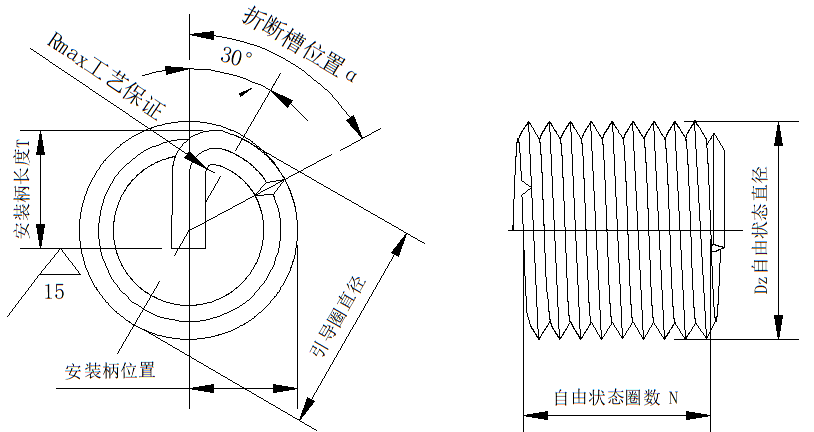
Note: See this figure for Table 2 & Table 3
Wire Thread Insert Standards
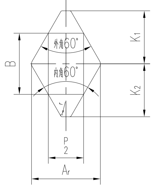
Table 4 GJB 119.4A-2001 Wire Thread Insert Parameters
Table 4 GJB 119.4A-2001 Wire Thread Insert Parameters
| Pitch P (mm) | Basic Dimension B(mm) | Upper Deviation B (μm) | Lower Deviation B (μm) | Basic Dimension K1(mm) | Upper Deviation K1 (μm) | Lower Deviation K (μm) | Basic Dimension K2(mm) | Upper Deviation K2 (μm) | Lower Deviation K2 (μm) | A min (mm) |
|---|---|---|---|---|---|---|---|---|---|---|
| 0.4 | 0.26 | 0 | -10 | 0.26 | 0 | -50 | 0.217 | 0 | -20 | 0.32 |
| 0.45 | 0.292 | -10 | 0.292 | 0 | -50 | 0.244 | 0 | -20 | 0.36 | |
| 0.5 | 0.325 | 0 | -10 | 0.325 | 0 | -60 | 0.271 | 0 | -25 | 0.4 |
| 0.7 | 0.455 | 0 | -10 | 0.455 | 0 | -60 | 0.379 | 0 | -25 | 0.56 |
| 0.8 | 0.52 | 0 | -12 | 0.52 | 0 | -60 | 0.433 | 0 | -40 | 0.64 |
| 1 | 0.65 | 0 | -12 | 0.65 | 0 | -90 | 0.541 | 0 | -40 | 0.8 |
| 1.25 | 0.812 | 0 | -12 | 0.812 | 0 | -90 | 0.677 | 0 | -55 | 1 |
| 1.5 | 0.974 | 0 | -13 | 0.974 | 0 | -120 | 0.812 | 0 | -55 | 1.2 |
| 1.75 | 1.137 | 0 | 1.137 | 0 | -120 | 0.947 | 0 | -70 | 1.4 | |
| 2 | 1.299 | 0 | -13 | 1.299 | 0 | -120 | 1.083 | 0 | -70 | 1.6 |
| 2.5 | 1.624 | 0 | -13 | 1.624 | 0 | -160 | 1.353 | 0 | -100 | 2 |
| 3 | 1.949 | 0 | -13 | 1.949 | 0 | -160 | 1.624 | 0 | -100 | 2.4 |
| 3.5 | 2.273 | 0 | -13 | 0 | -200 | 1.894 | 0 | -120 | ||
| 4 | 2.598 | 0 | -13 | 2.598 | 0 | -200 | 2.165 | 0 | 3.2 |
Industry Application Challenges & Solutions
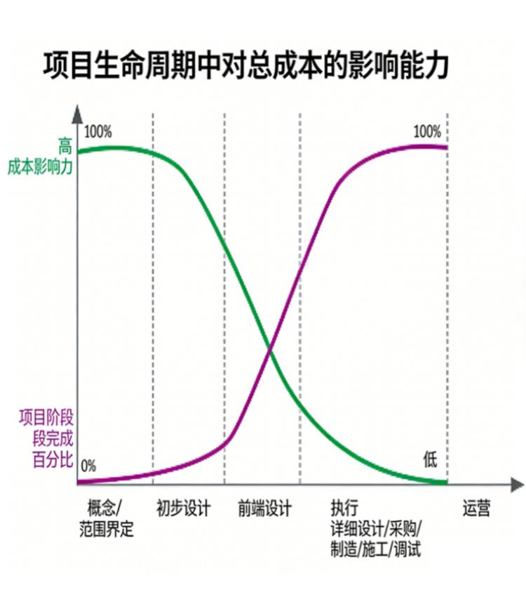
Project Cycle Cost Impact Model
In today's rapidly developing society, the core challenge faced by enterprise R&D is: the early decision-making window is extremely short but locks in most of the costs; while the later stage involves huge investment with extremely high error correction costs, leading to a serious mismatch between risks and benefits. This requires enterprises to make accurate judgments at the very early stage to cope with market uncertainties.
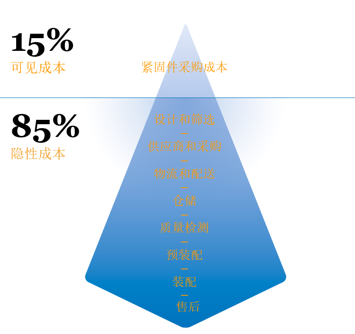
15-85 Rule
Excessive focus on explicit procurement costs while ignoring the 85% proportion of hidden costs leads to the lack of systematic coordination in design, supply chain, after-sales and other links, greatly pushing up the total life cycle cost.
Six Professional Services of Yingfeng Zhichengjia


Summary
As a high-performance internal thread reinforcement component, wire thread inserts are widely used in industrial fields with high requirements for thread strength, wear resistance and reliability. Through standardized installation processes and diversified specification selection, they can perfectly solve industry pain points such as insufficient thread strength, easy damage and easy loosening of soft materials, effectively improve the overall stability and service life of equipment, and are the preferred solution for modern industrial fastening connections.